End result
 The preamp.
Due to a design flaw, the provided preamp board is too big to fit into the box. Cutting it to fit is possible but requires some careful carving.
 Encoderboard and buttonboard.
 Neopixelboard
Etching
Your need to etch 4 different boards:
- the preamp,
- the encoderboard,
- the NEO-pixel board, and
- the button board.
PCB layouts are provided in the file list of this page.
In difference to the PCBs for the mainboard and the capsense sensors, which are multilayer PCBs and therefore need to be professionally manufactured, these PCBs can be etched by yourself. However:
It needs some experience to get good results. Furthermore one has to take care with the highly toxic and acidic liquits!
We do not provide a general introduction into etching, but there are plenty around on the web.
 Always wear protective clothing when operating chemicals.
 Exposure of the cirquit boards with UV light.
 PCB in developer liquit.
 PCB in stopping liquit.
 Acid bubble bath
 Completed PCB
Drilling
Use a small upright drilling machine. For most electronic parts a 1mm drill is fine. for encoder mount points use a 2mm drill. PCB mounting holes are 3mm.
 Drilling holes.
 placing encoders. mount point holes need to be 2mm.
Soldering
As for all electronic parts, we assume basic skills in soldering.
If you do not have those, we recomment you ask your local guru to help you out.
We do not provide a general introduction into soldering, but there are plenty around on the web. In general, always start with the lowest parts.
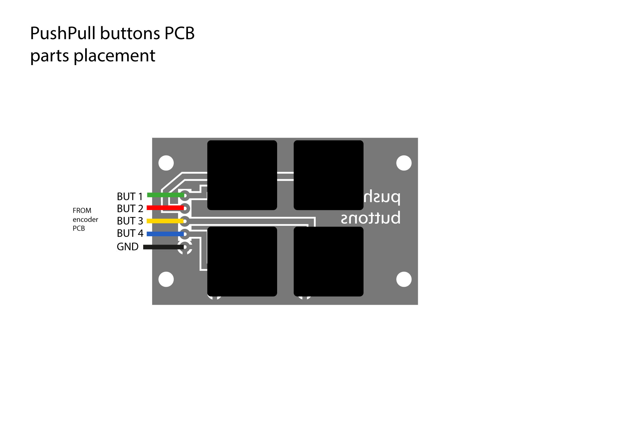 Buttonboard component placement.
 Encoderboard component placement.
 Neopixboard component placement.
 Preamp component placement.
 Placement of components.
 Soldering.
Encoder code upload
Button states and rotary encoder states are processed by an ATMEL Atmega 328 Chip. It then sends the data by a serial connection to the X-OSC module. The ATMEL needs to be programmed with the Arduino IDE.
The particular code for this system is available here.
Before you can upload the code, you need to install a bootloader to the ATMEL chip. Setting up, bootloading and uploading arduino code to a vanilla Atmega using a breadboard and a FTDI breakoutboard is described here. The hardware setup found in this tutorial was also the basis on which we designed the encoderboard itself.
Crimping cables
You need to add cables to the boards in approriate lengths. For some of the contacts we used plugs which makes it easy to (dis)assemble the PushPull. Here are some impressions of the crimping process. A bill of materials for the crimping can be found here.


