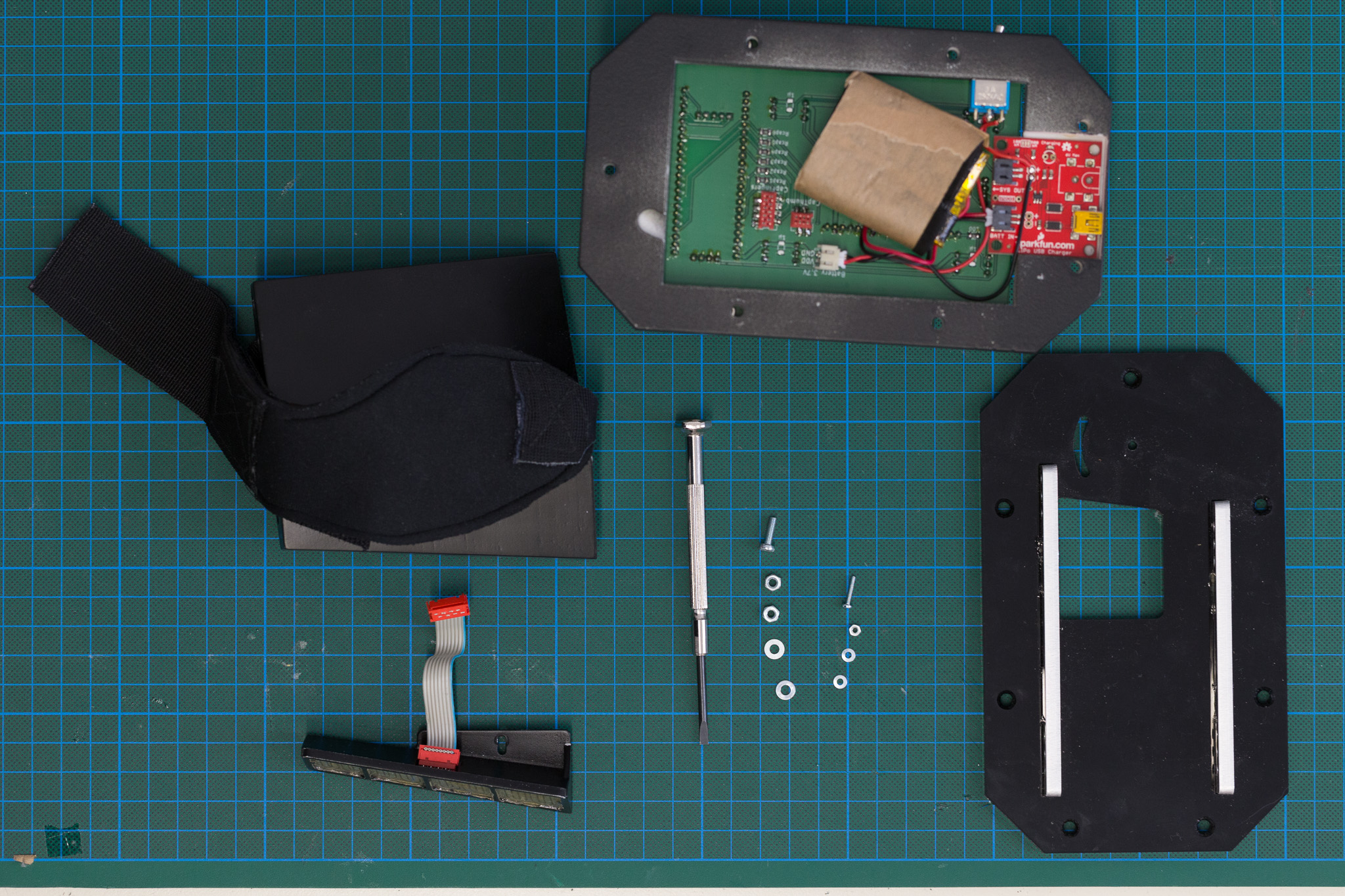
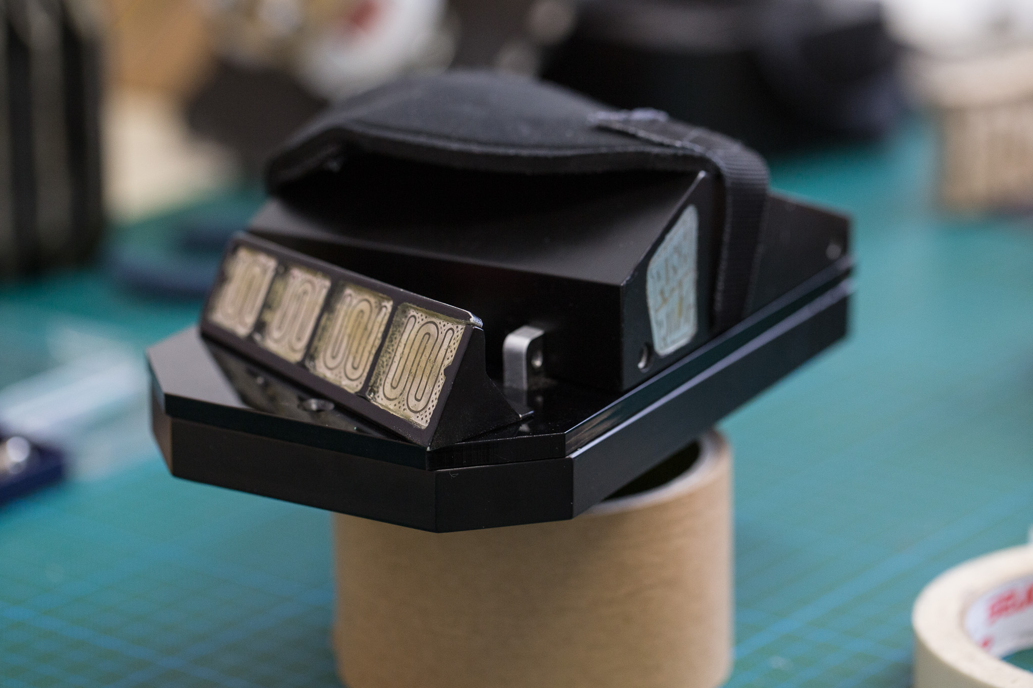
End result
Soldering
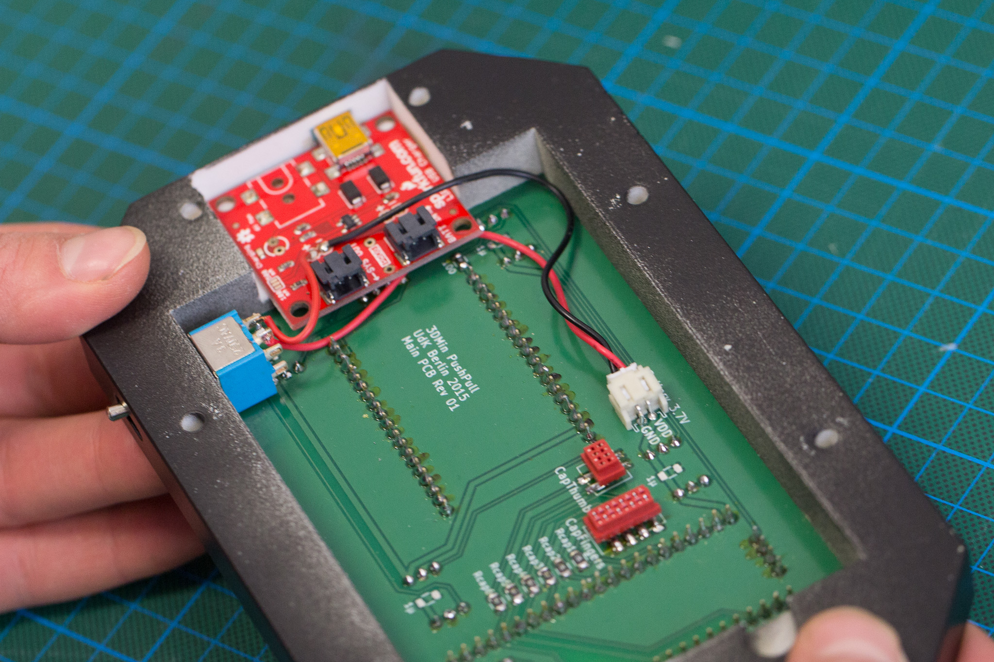
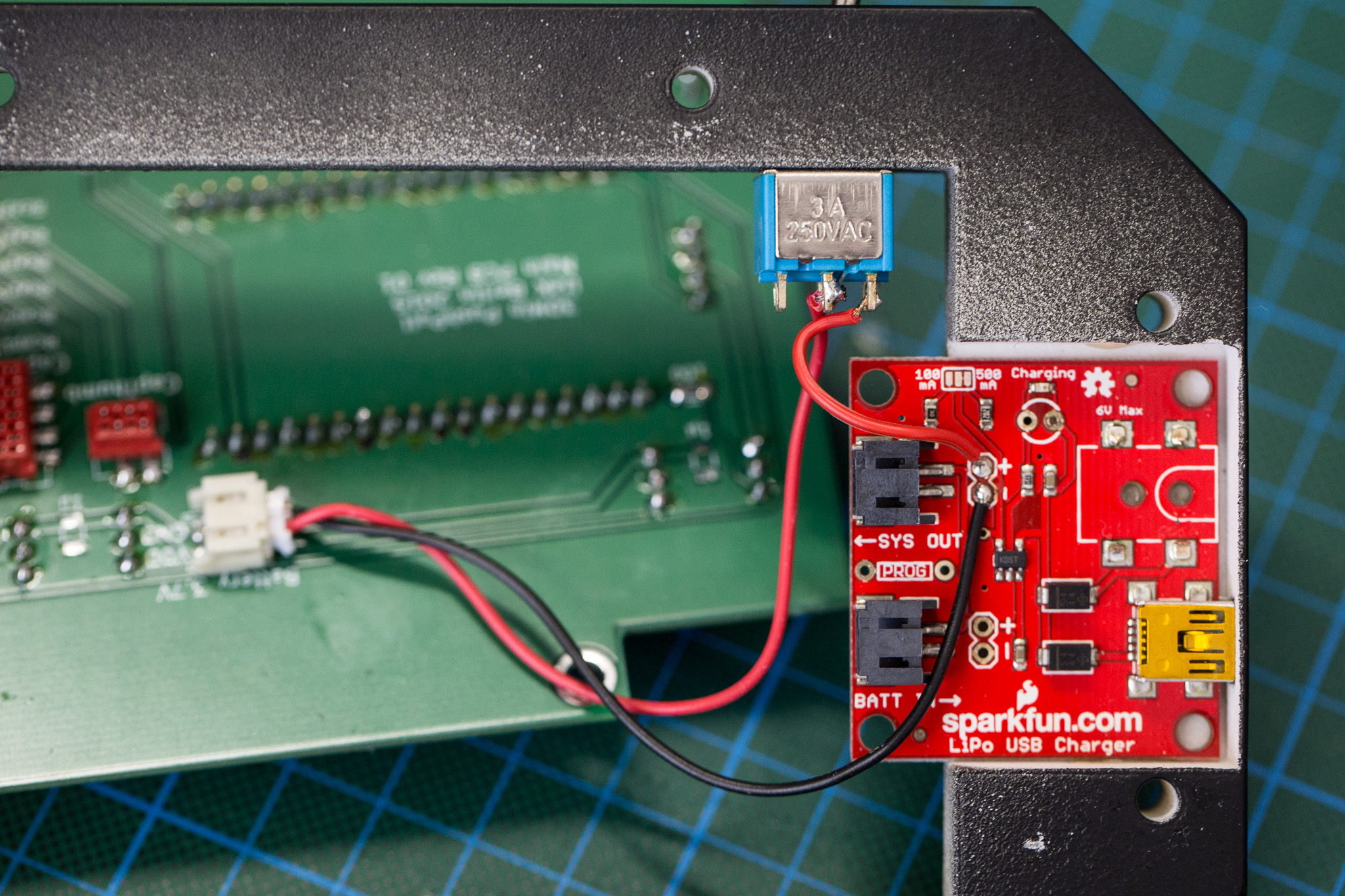 soldered connections between USB charger, switch and mainboard
Frame assembly
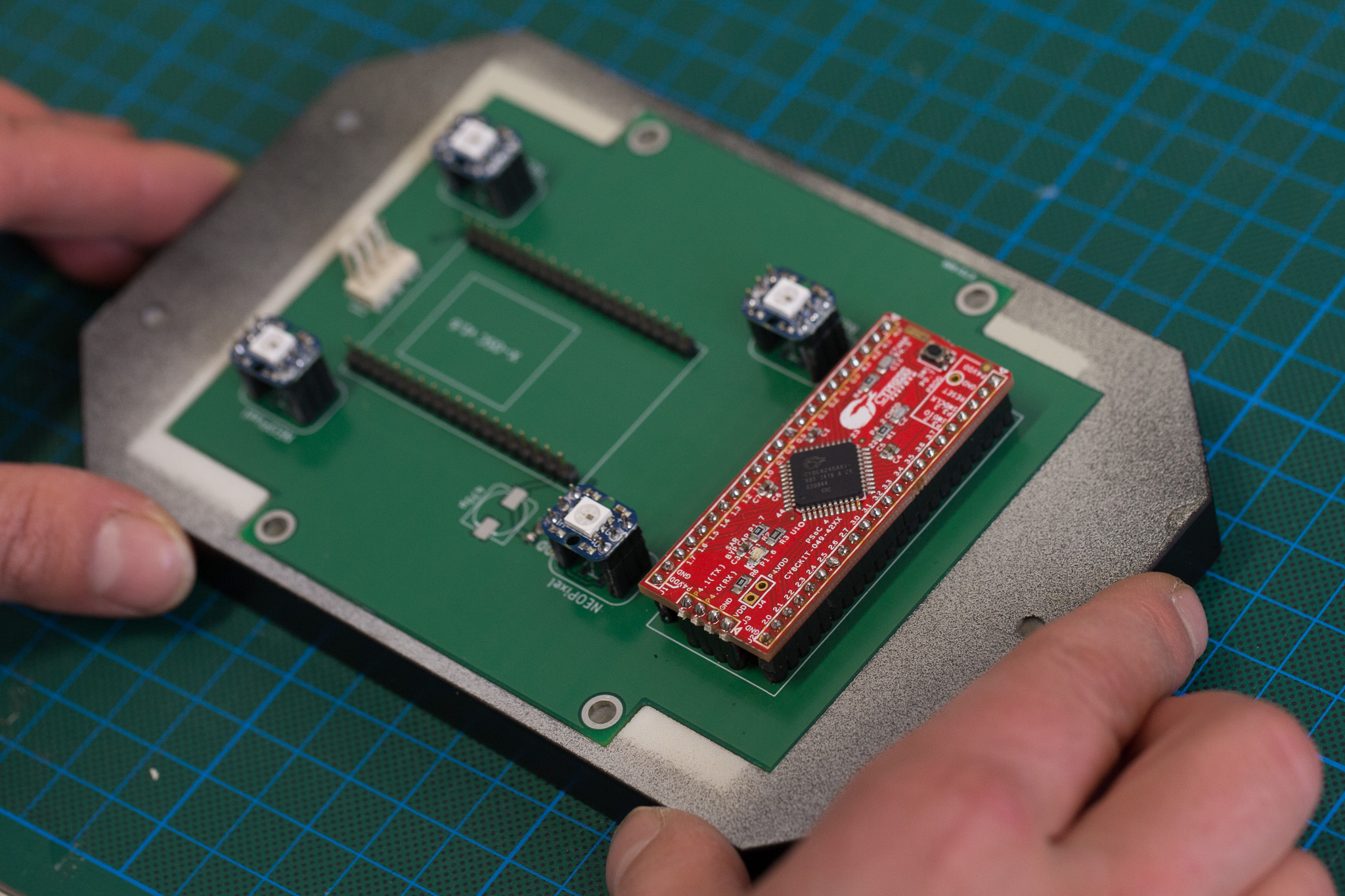 bellow-facing side of the frame for the mainboard
 top-facing side of the fully assembled frame.
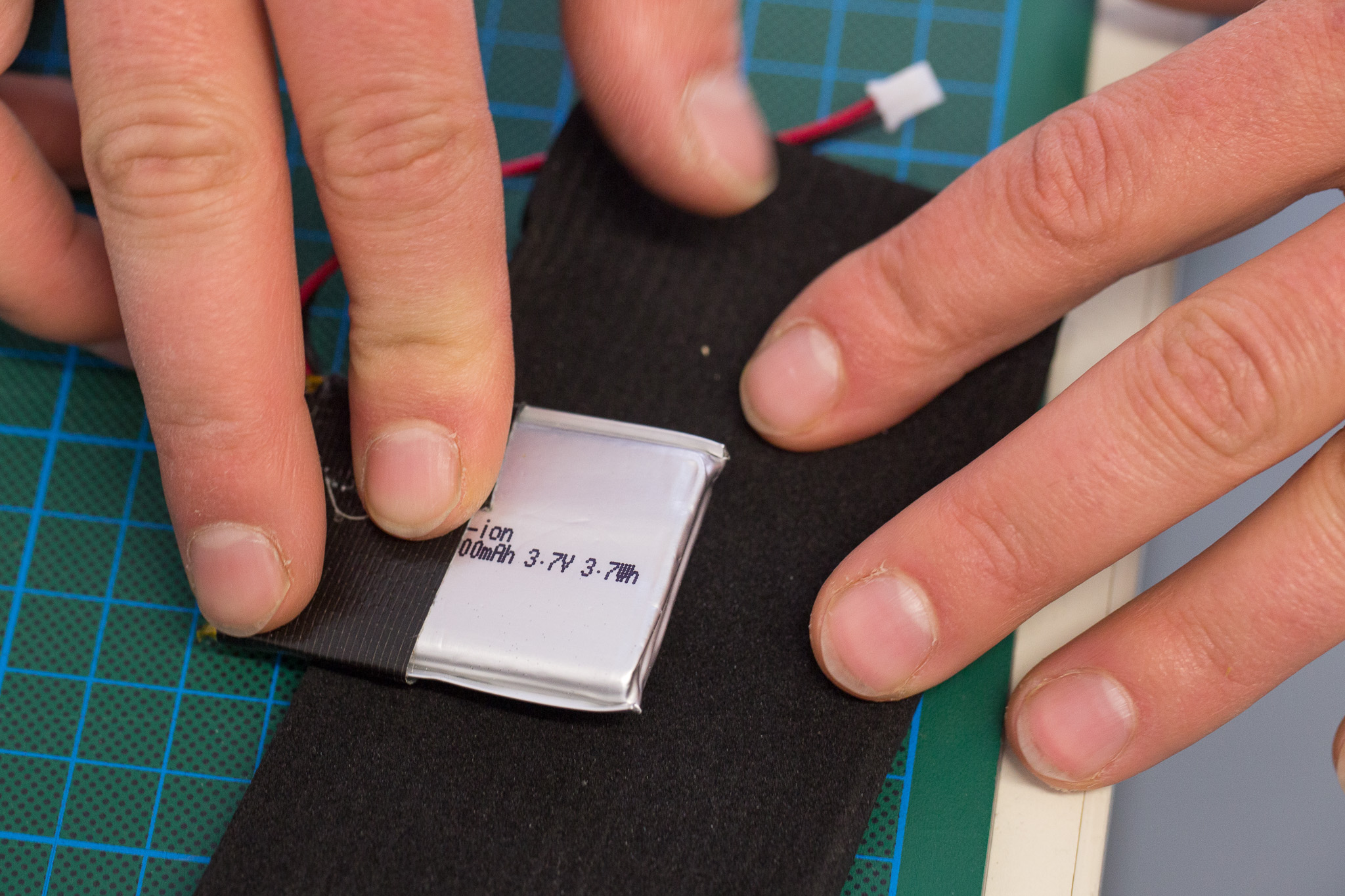 Wrapping the LiPo into cloth prevents it from being pierced by soldered pins of the mainboard.
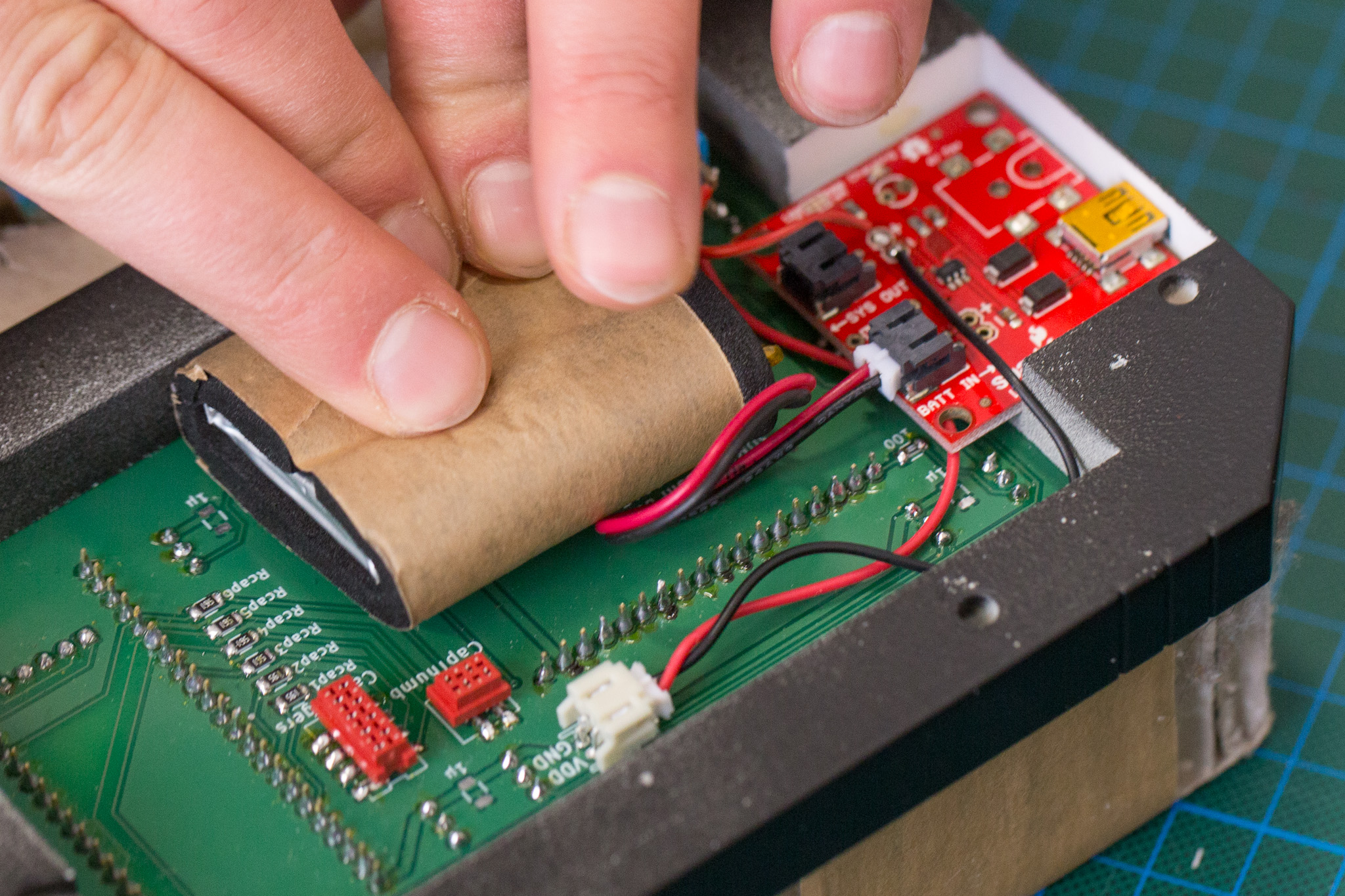 make sure the LiPo fits into the space between upper part and mainboard.
Sensor board assembly
Attach the cables to the thumb sensor area, thread its cable through the hole in the handpiece top and press the sensor board into its cavity.
Be sure to know that you dont need to access their back anymore, it might be increadibly hard to get them back out.
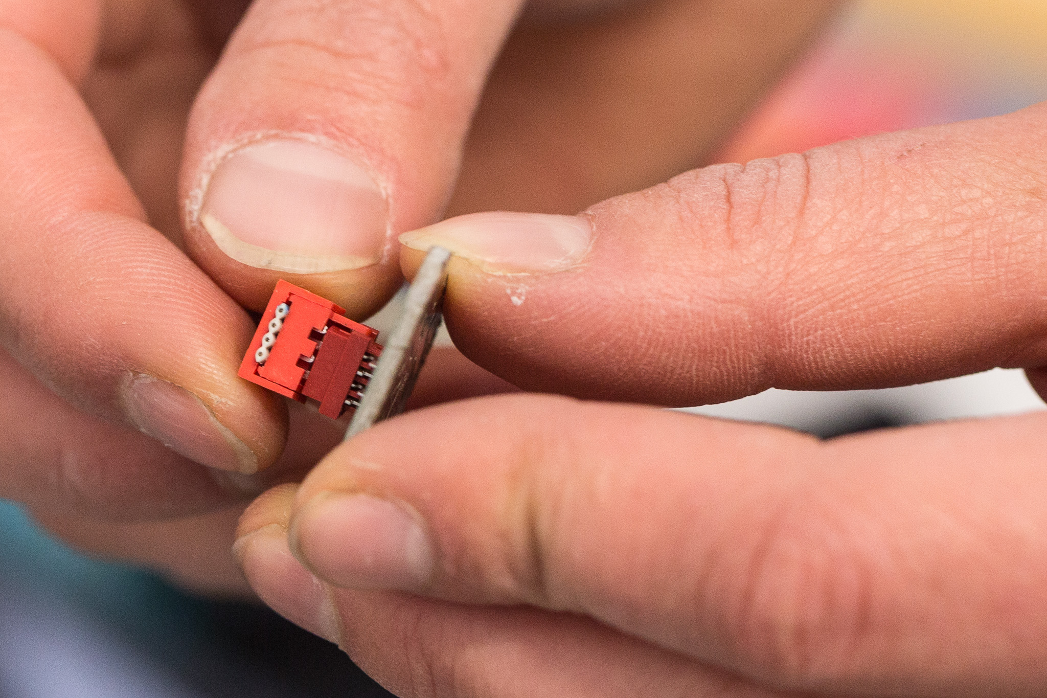 attach the cables to the thumb sensor area.
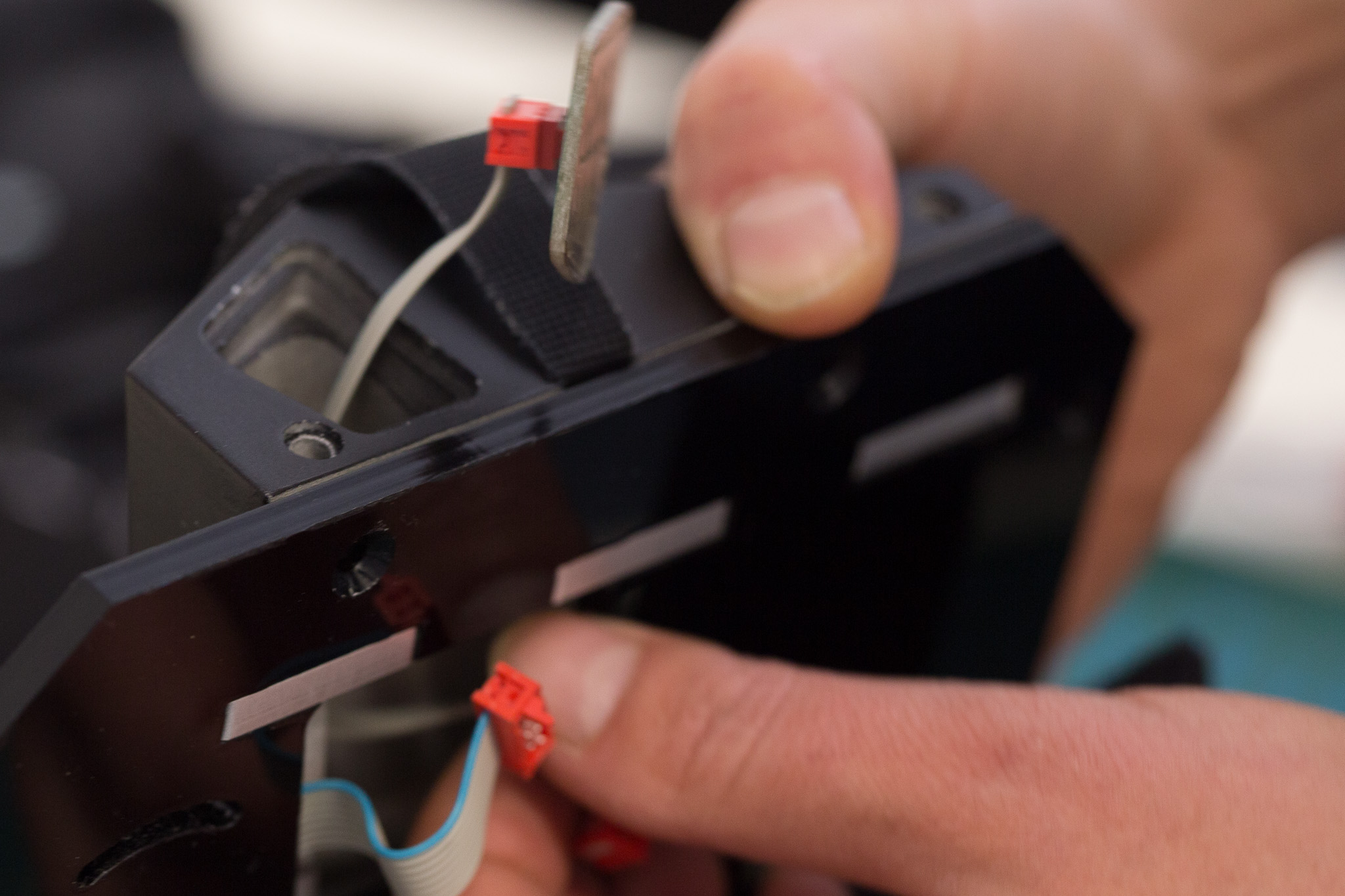 Thread the thumb cable through the hole
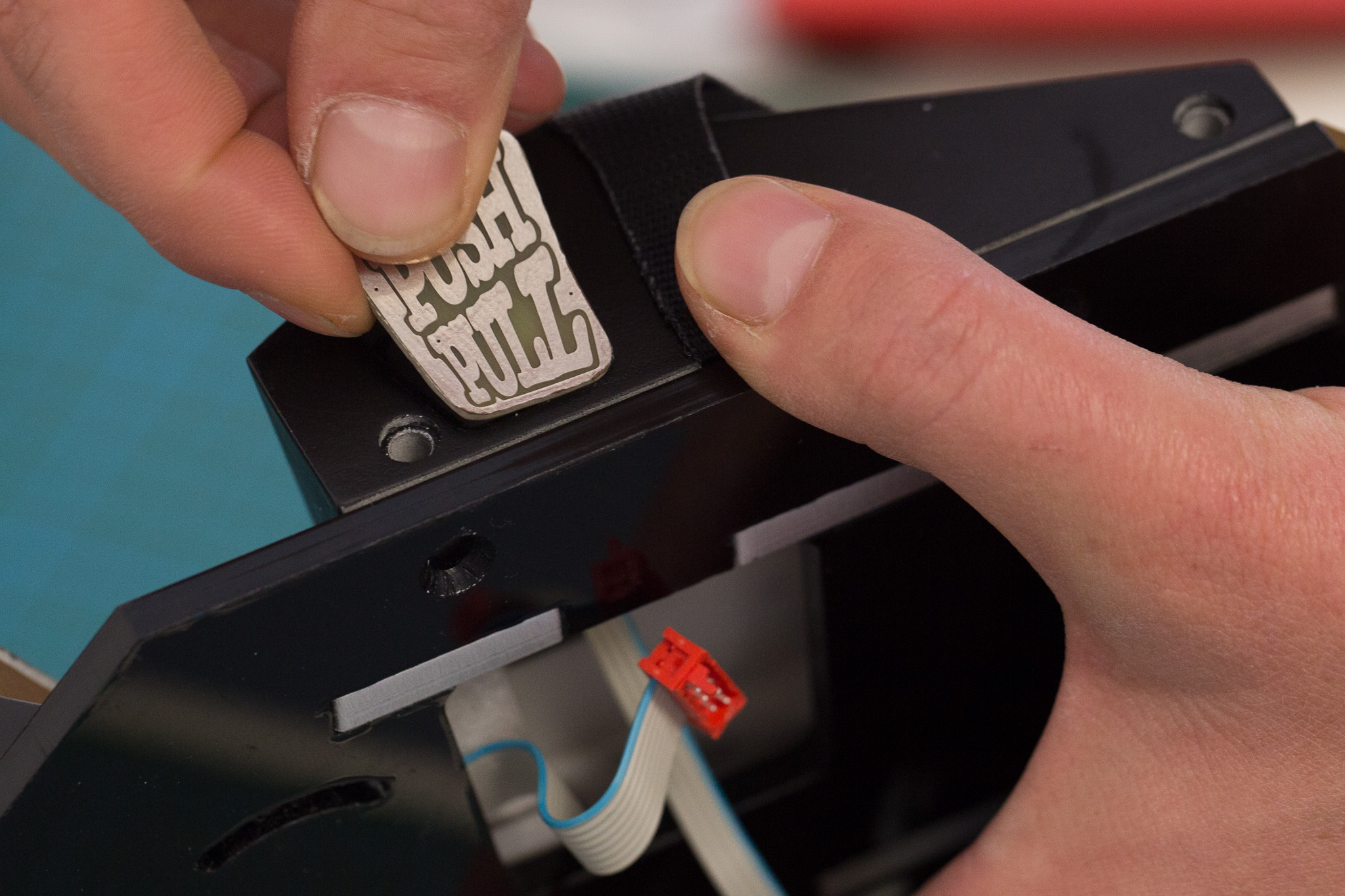 attach the thumb area to the hand piece
Clip the capacative finger sensors into the fingerboard. Their plug fits into the rear cutout. Then glue the fingerboard skeleton on top.
Attach the fingerboard support to the acryllic base plate and attach its cable.
The cables of both sensors should appear through the hole in the base plate.
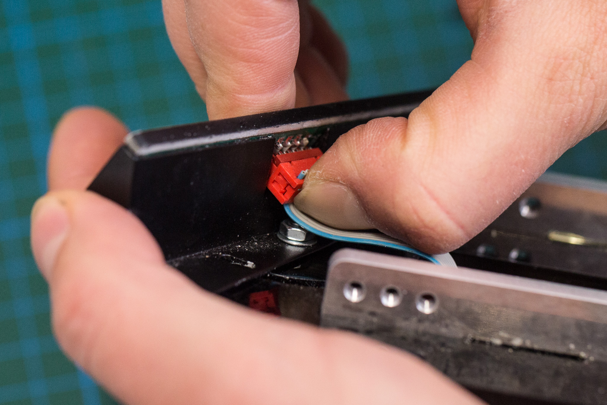
Attach them to the plugs on the mainboard.
before tightening any screws (also later!), make sure the cable runs through the cutout between top piece and base plate.*
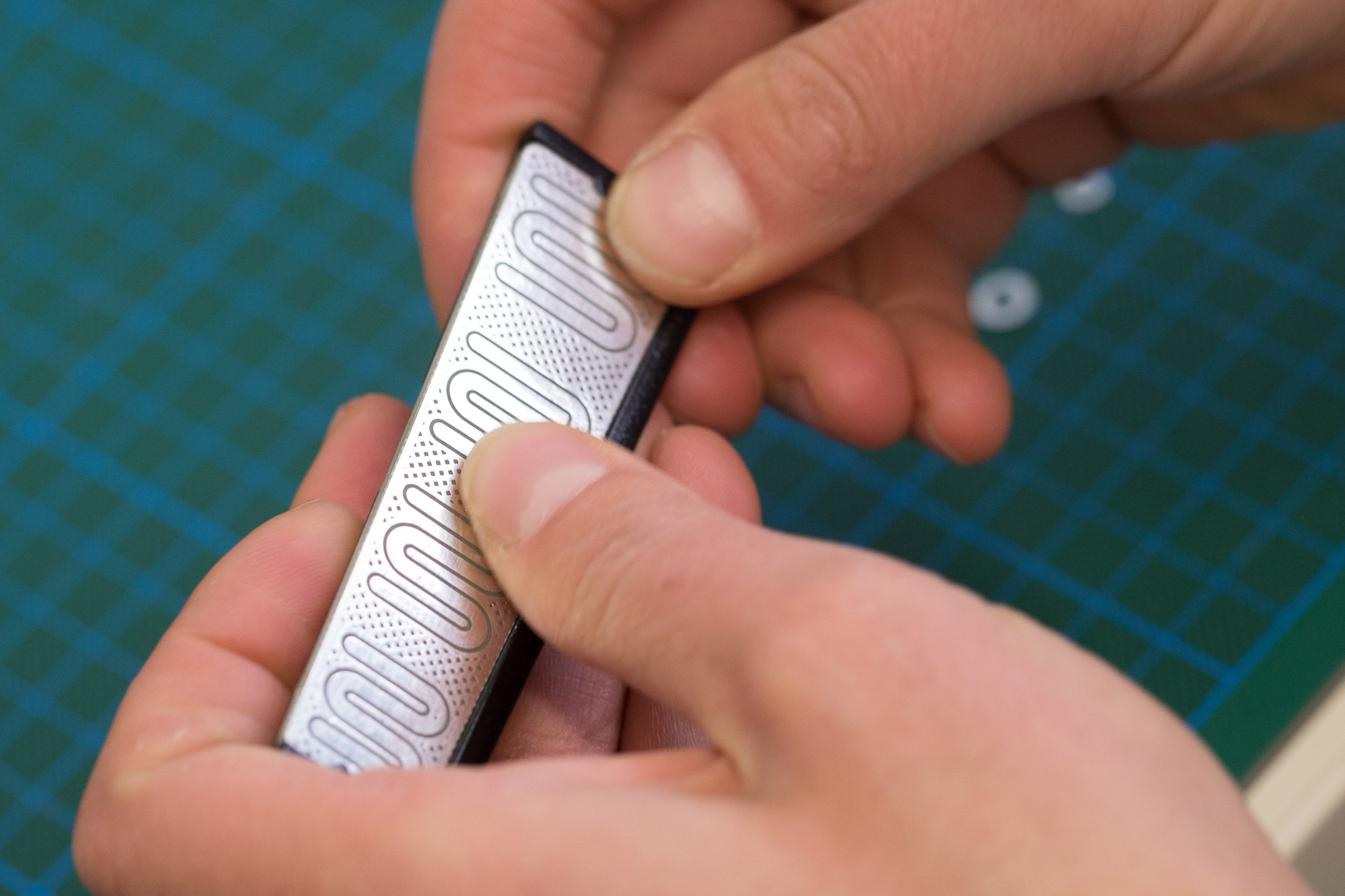 clip the finger board into its support
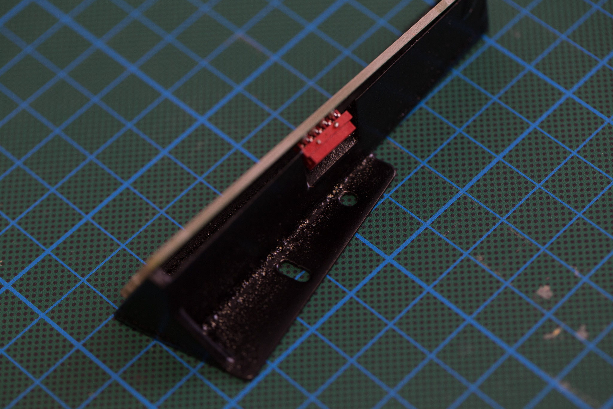 the plug of the finger sensor fits into the rear cutout of its support
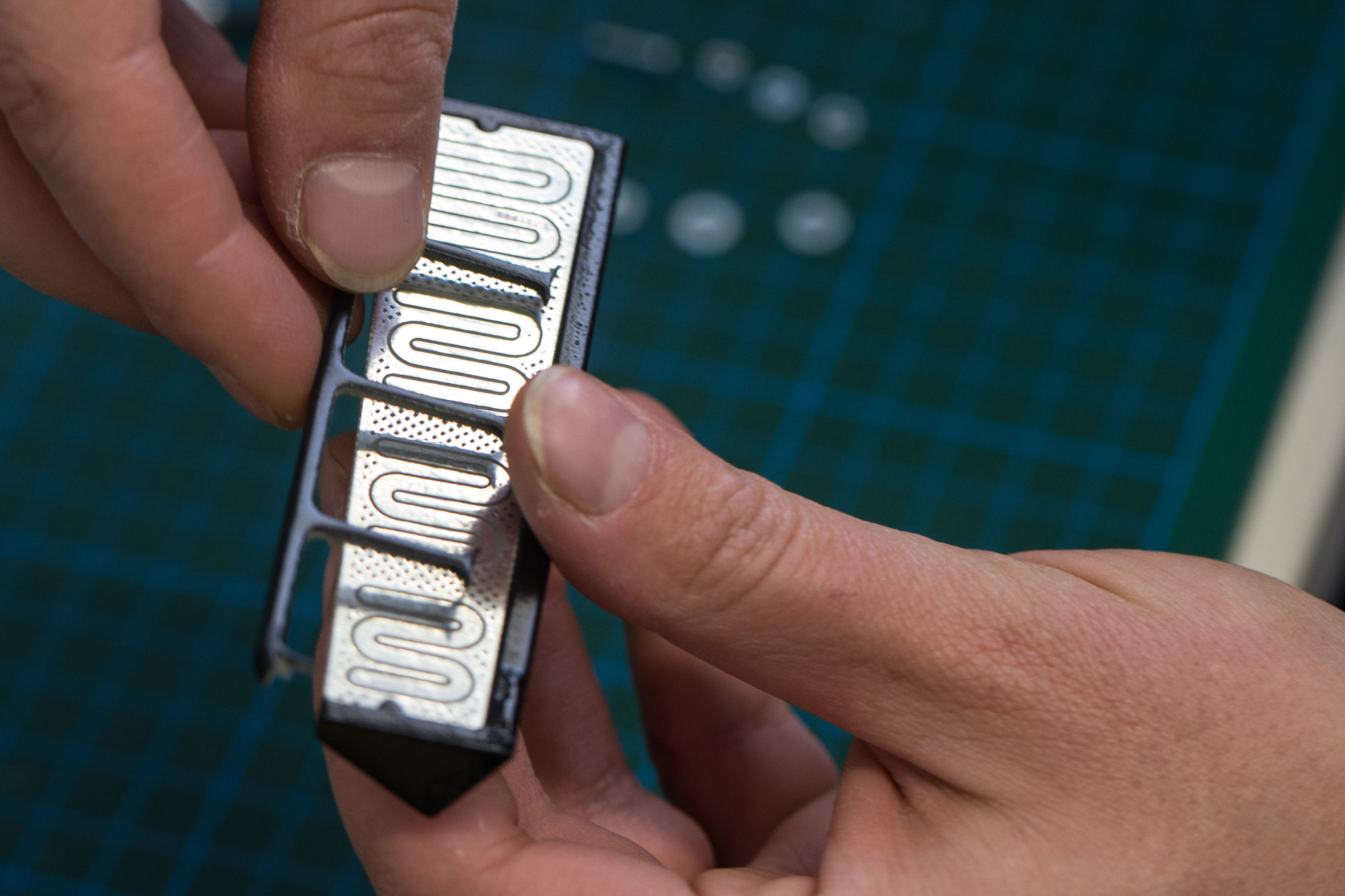 glue the fingerboard skeleton on top.
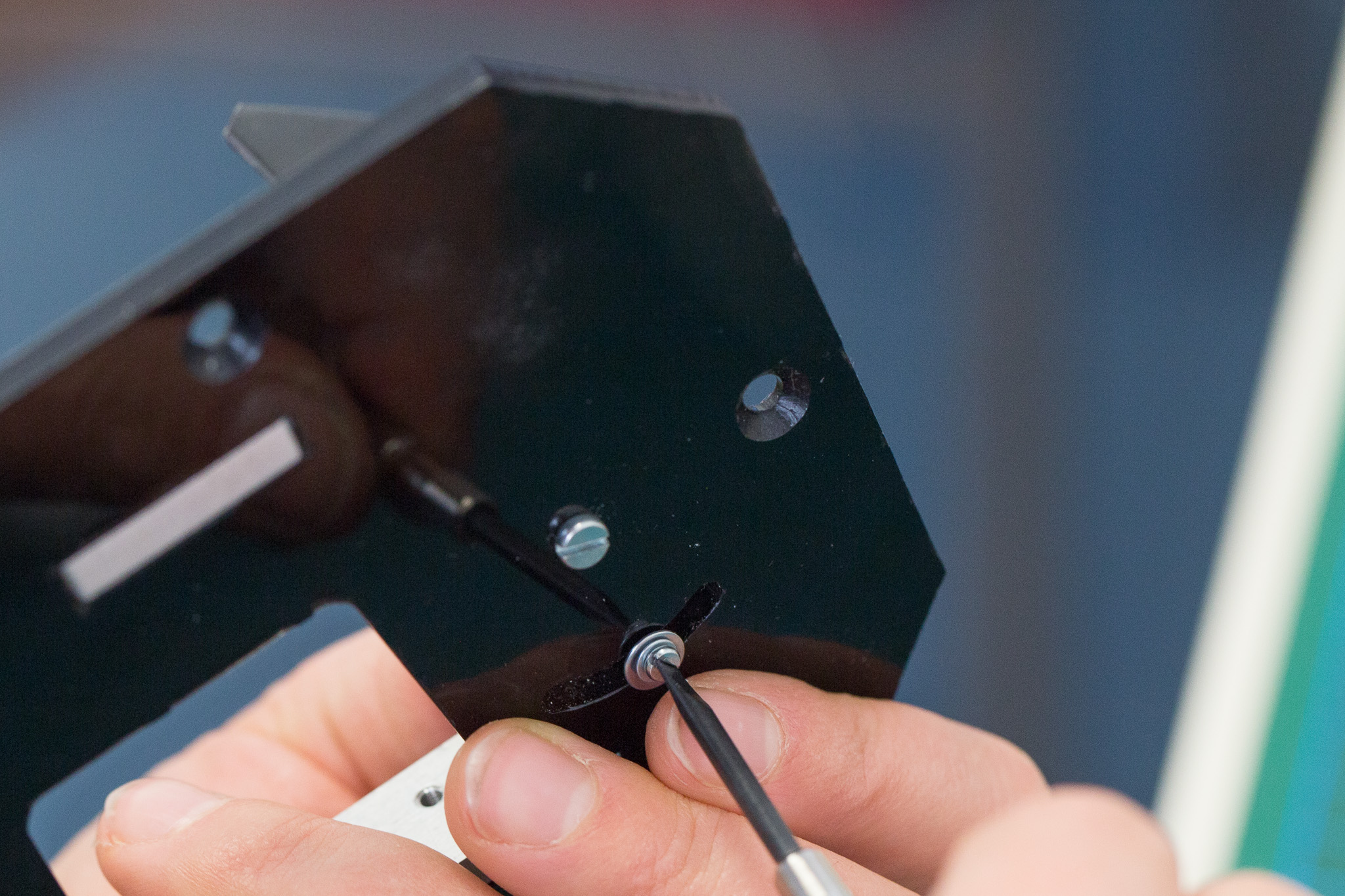 attach the fingerboard support to the acryllic base plate
 clip the cable to the fingerboard
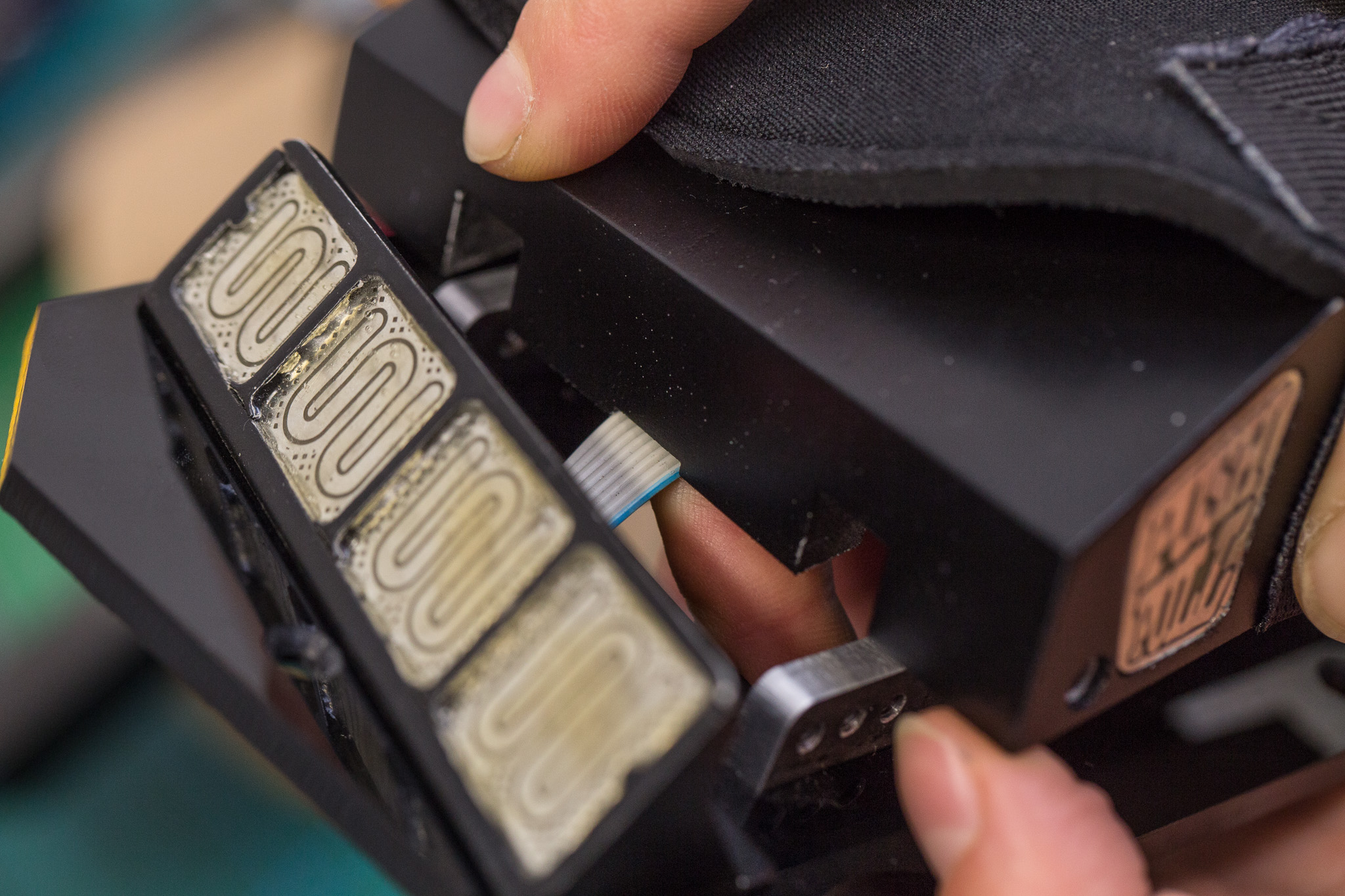 before tightening any screws (also later!), make sure the cable runs through the cutout between top piece and base plate.
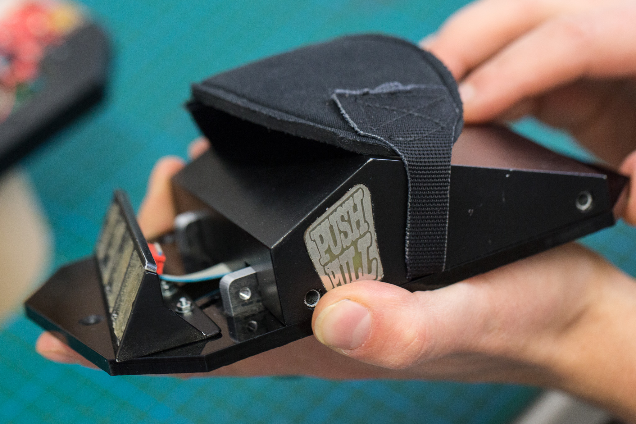 baseplate with sensor boards and hand piece.
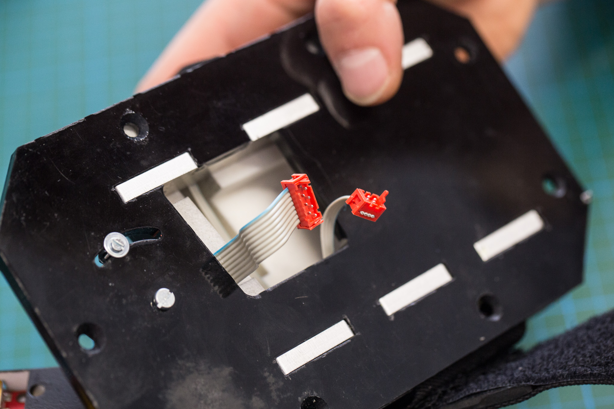 the cables appear through the hole in the base plate.
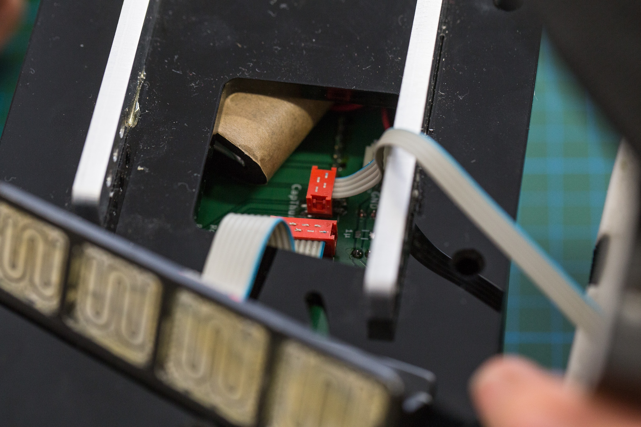 attach them to the plugs on the mainboard.
 the assembled hand piece


 soldered connections between USB charger, switch and mainboard
 bellow-facing side of the frame for the mainboard
 top-facing side of the fully assembled frame.
 Wrapping the LiPo into cloth prevents it from being pierced by soldered pins of the mainboard.
 make sure the LiPo fits into the space between upper part and mainboard.
 attach the cables to the thumb sensor area.
 Thread the thumb cable through the hole
 attach the thumb area to the hand piece
 clip the finger board into its support
 the plug of the finger sensor fits into the rear cutout of its support
 glue the fingerboard skeleton on top.
 attach the fingerboard support to the acryllic base plate
 clip the cable to the fingerboard
 before tightening any screws (also later!), make sure the cable runs through the cutout between top piece and base plate.
 baseplate with sensor boards and hand piece.
 the cables appear through the hole in the base plate.
 attach them to the plugs on the mainboard.