Mainboard and capsense steps
Tools
- tweezers
- soldering iron
- pliers
- (old proto-board, if available)
Materials
- pcbs
- thin solder
- electronics from partlist (see Files)
- x-OSC from x-io technologies
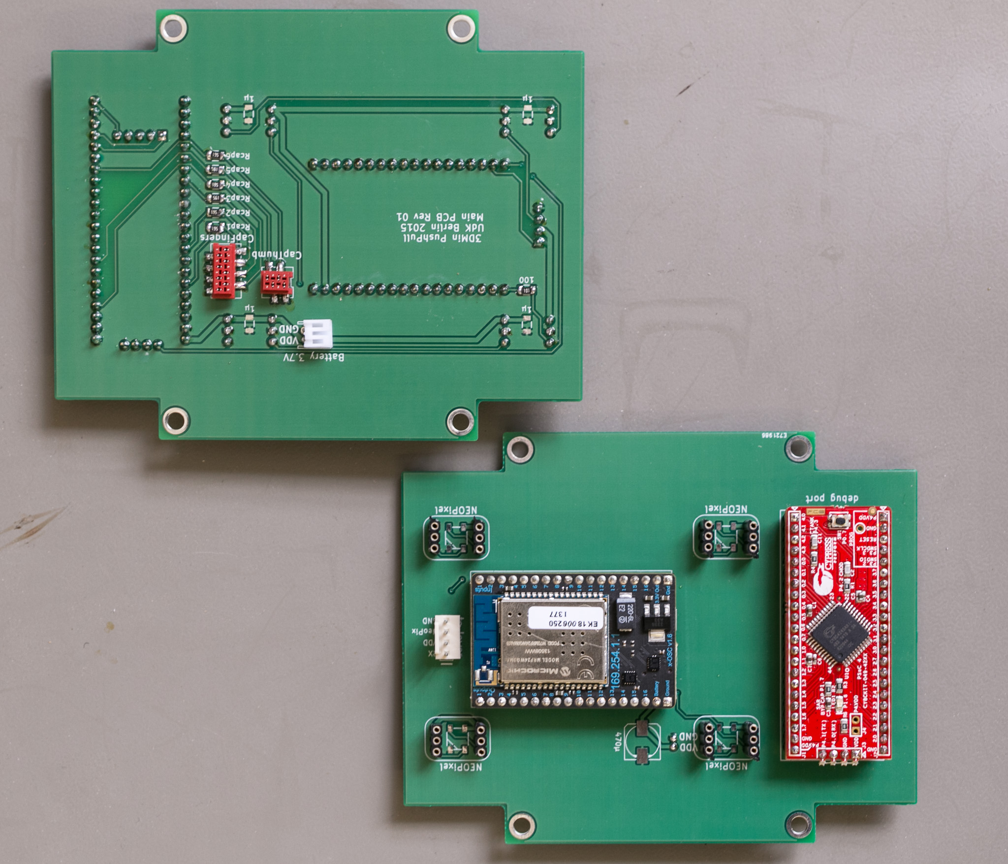 Mainboard with attached X-OSC.
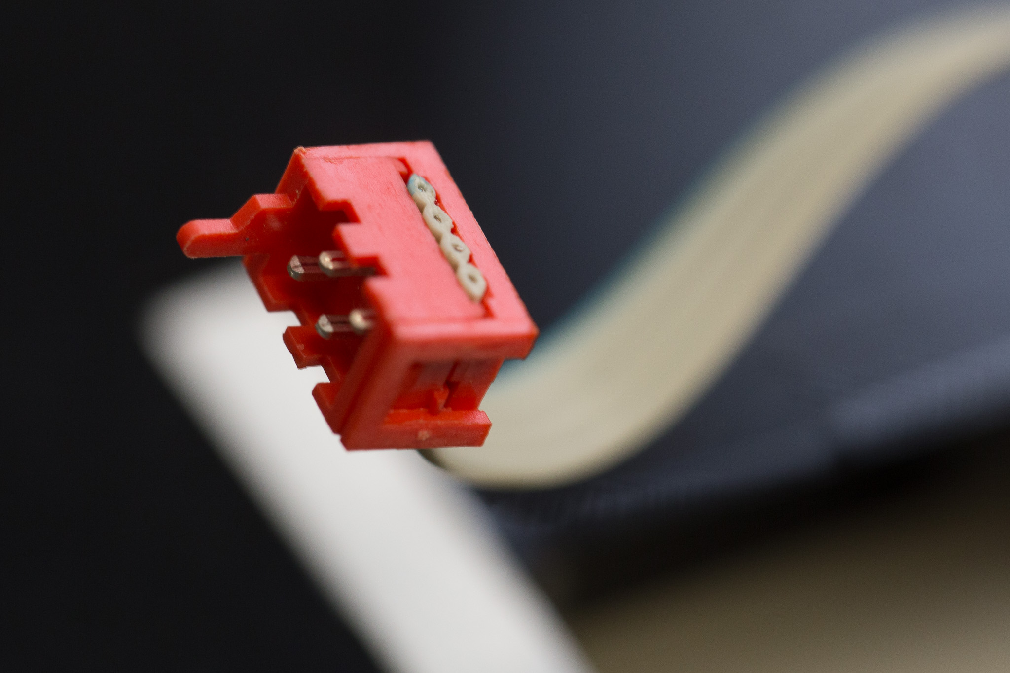 Crimped cable
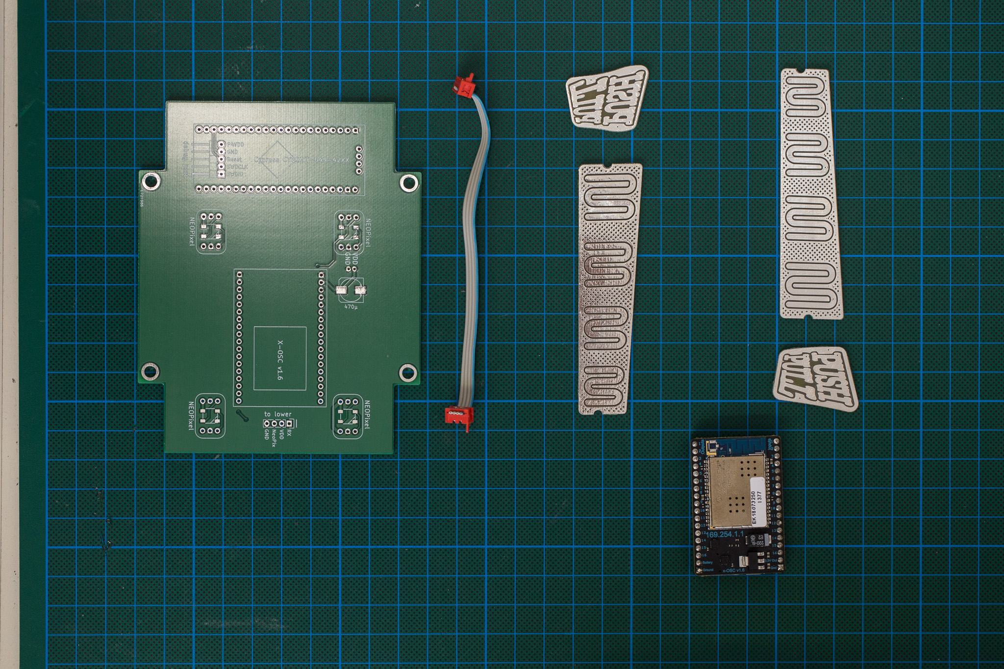 The PCBs (both, left-handed and right-handed versions of the sensor areas are shown).
Both, the mainboard as well as the capsense PCBs are multilayer circuit boards and therefore cannot be etched at home. Download the corresponding KiCad files from the files section above and send them to a professional circuit board manufacturer.
The kicad files for the circuit boards can be found in this repository.
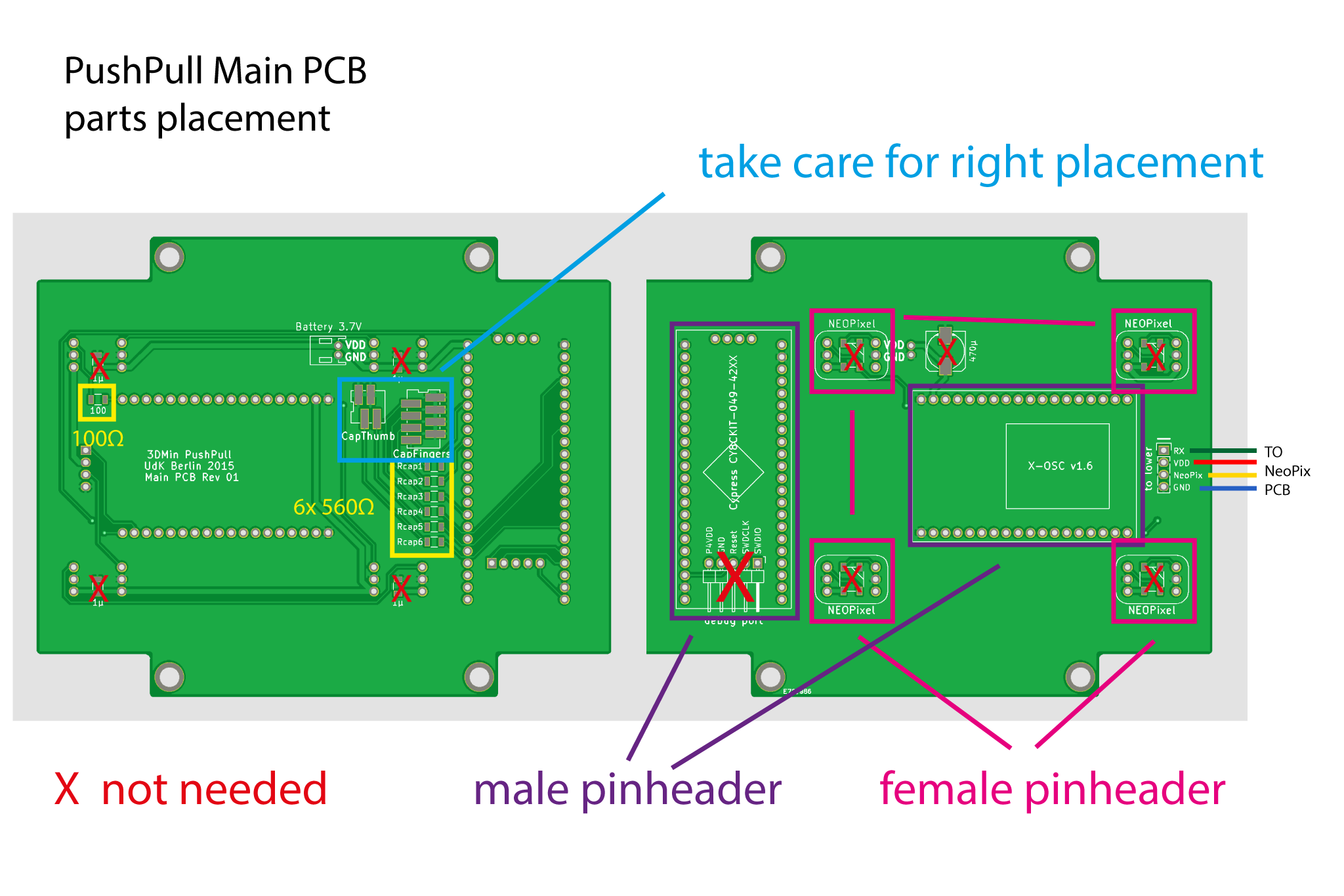 Obsolete parts are marked with a red X. A larger version of this drawing can be found in the Files section above.
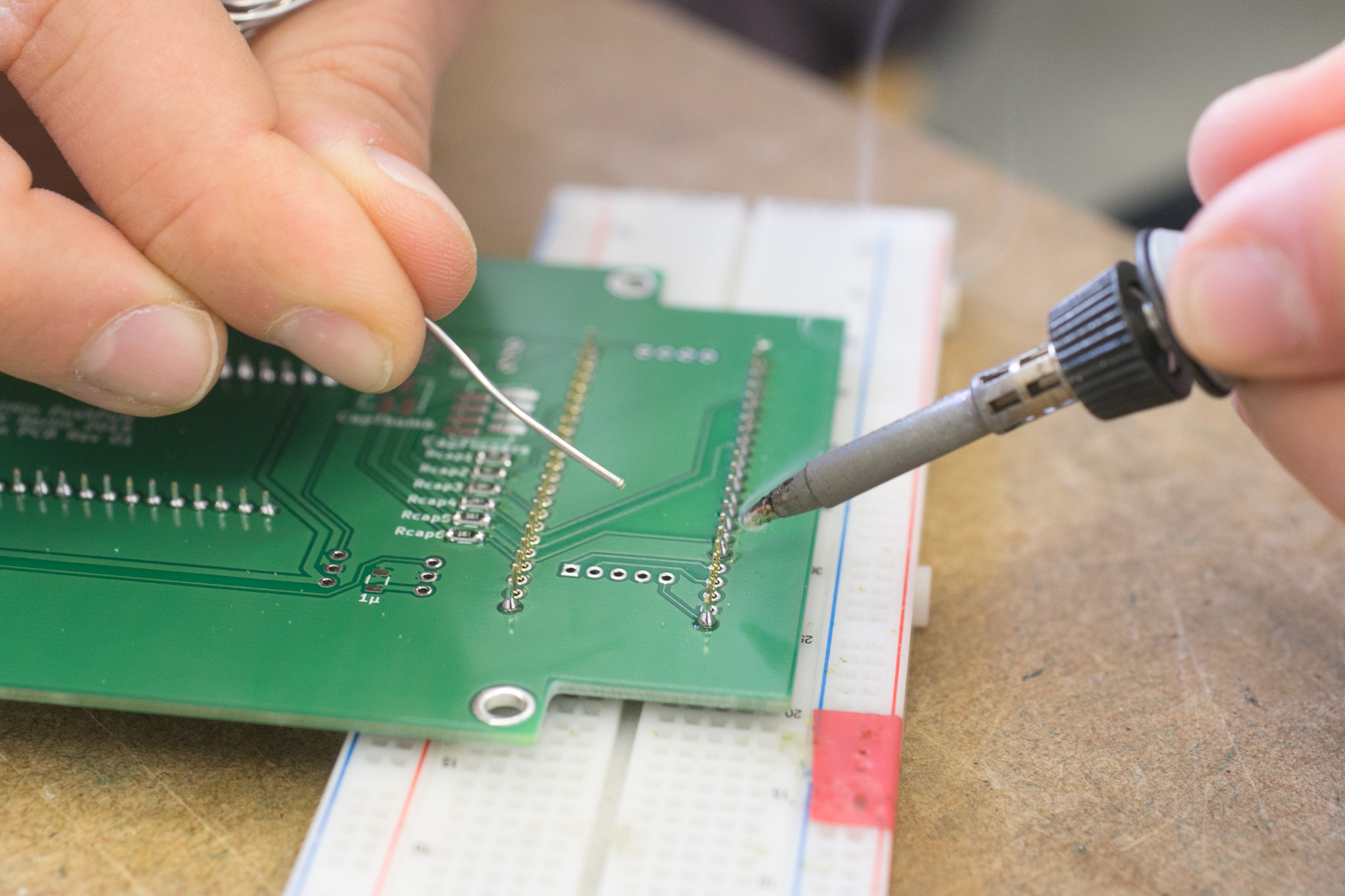
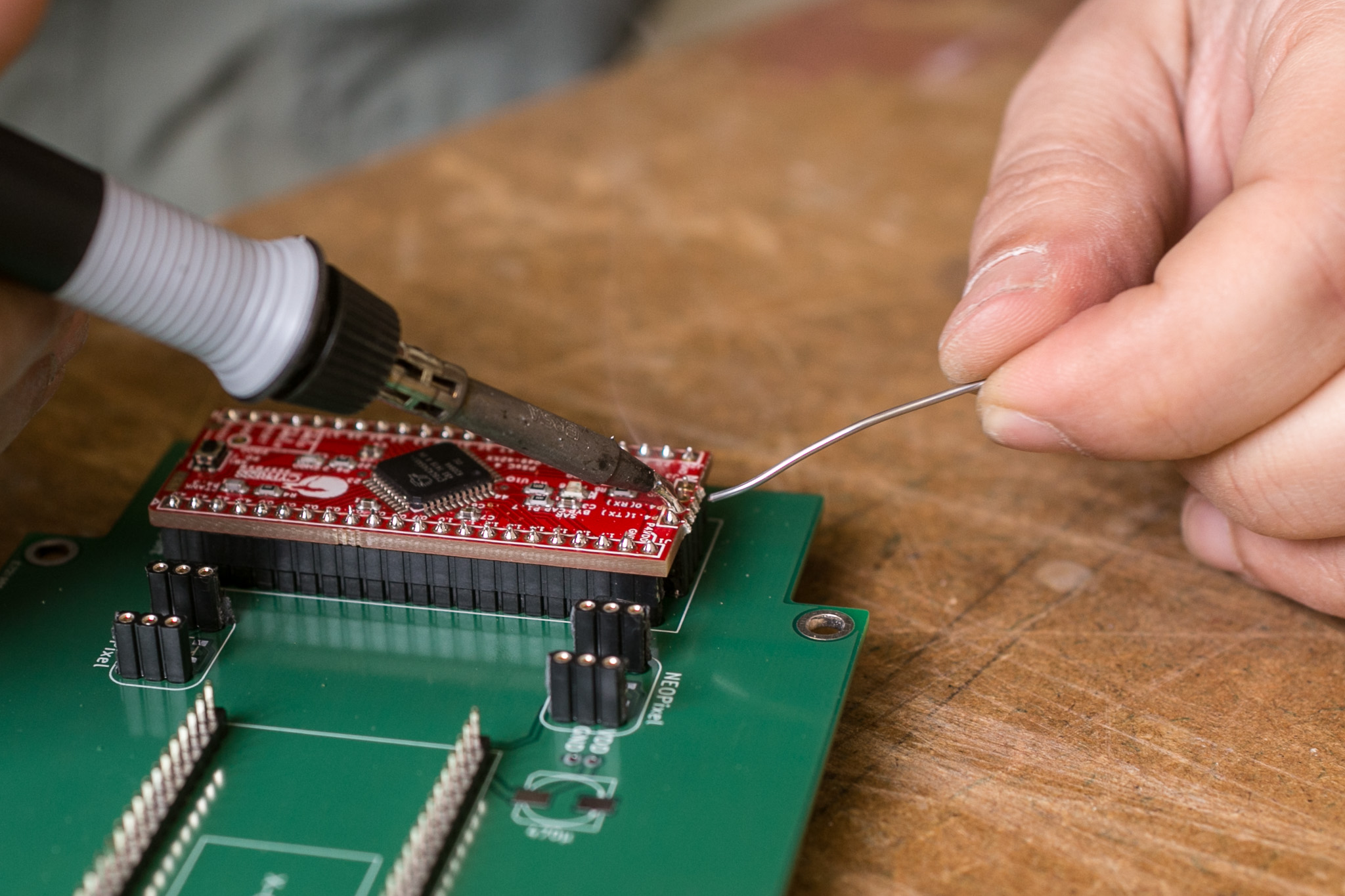
As for all electronic parts, we assume basic skills in soldering. If you do not have those, we recommend you ask your local guru to help you out. We do not provide a general introduction into soldering, but there are plenty around on the web. Also for SMD soldering by hand using tweezers which is needed here. In general, always start with the lowest parts. An old proto-board that is not needed any more can be used as helping hand to get the male pin headers soldered straight to the PCB. The proto-board will eventually melt, so do not use a new one that you want to reuse later. Here are some impressions:
 Soldering the pin headers.
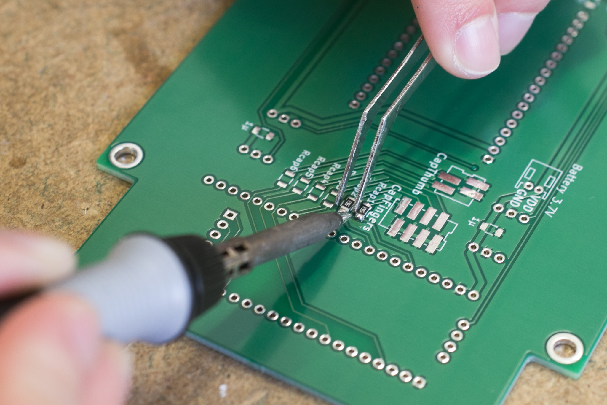 Use tweezers to secure SMD parts while soldering.
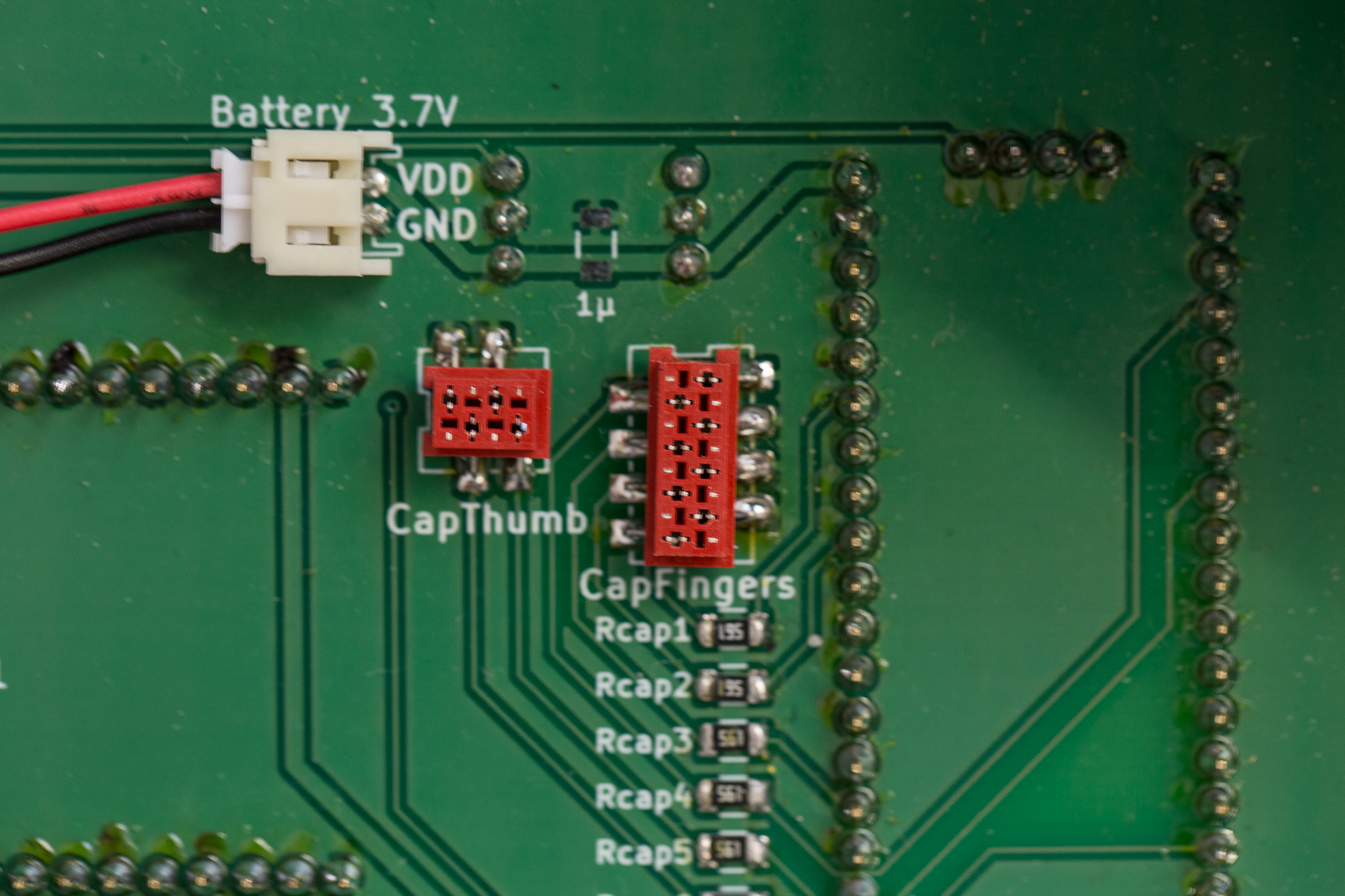 Plugs for Capsesnse connection on mainboard
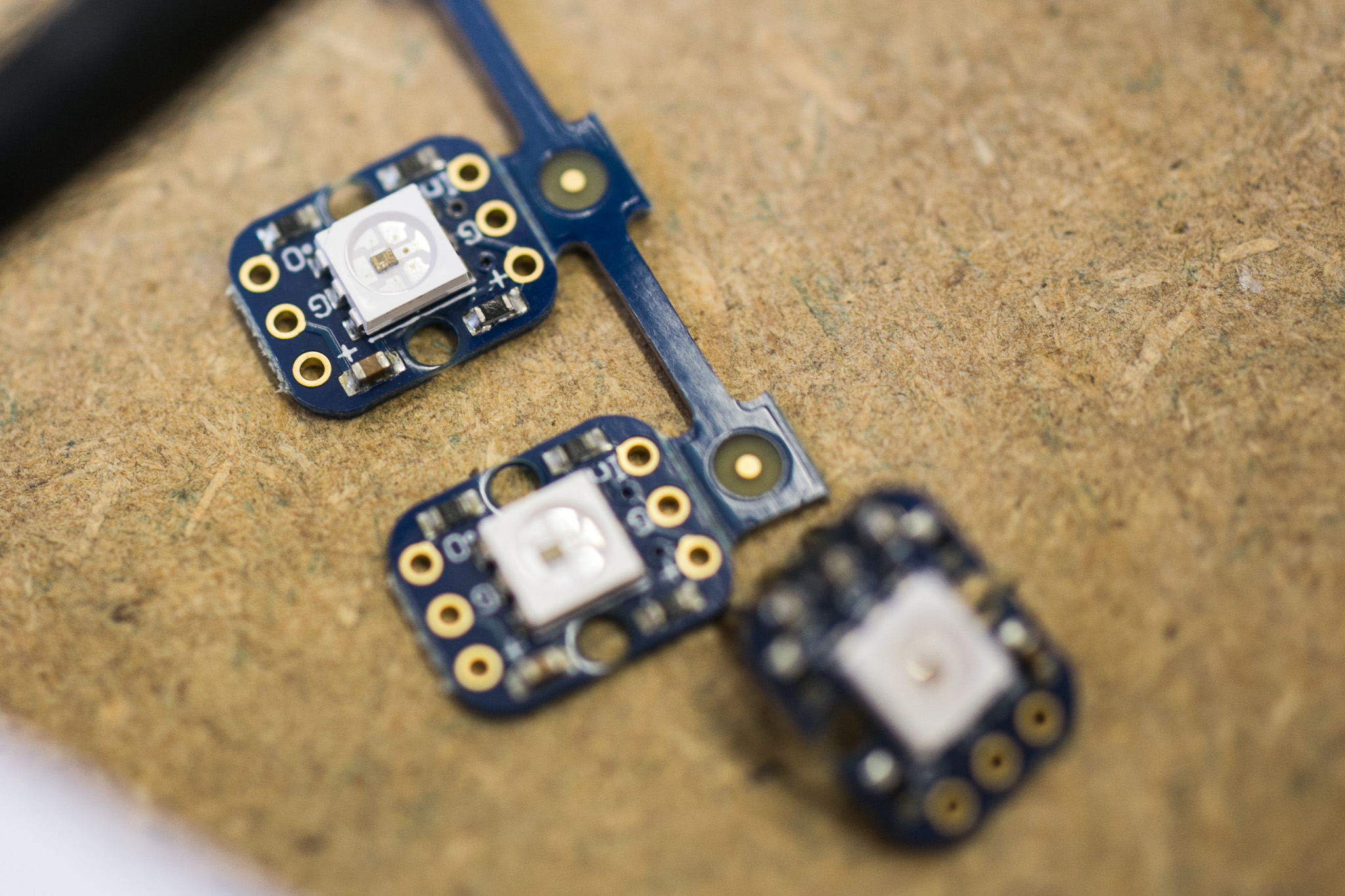
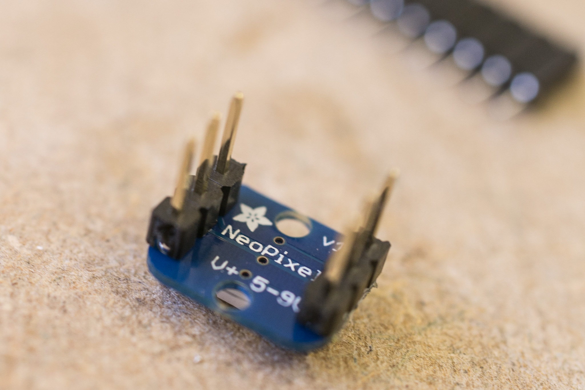
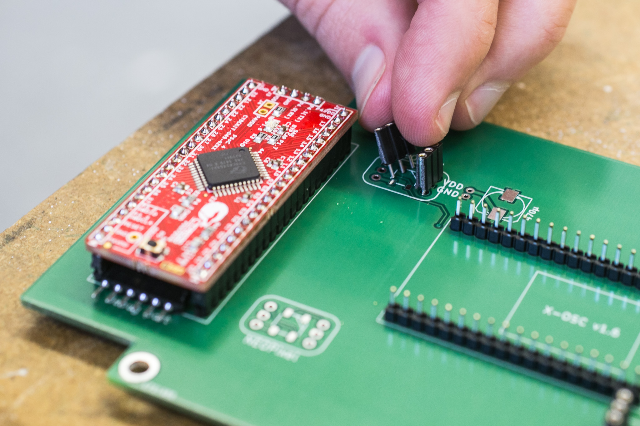 Add pin headers to Neopixel areas.
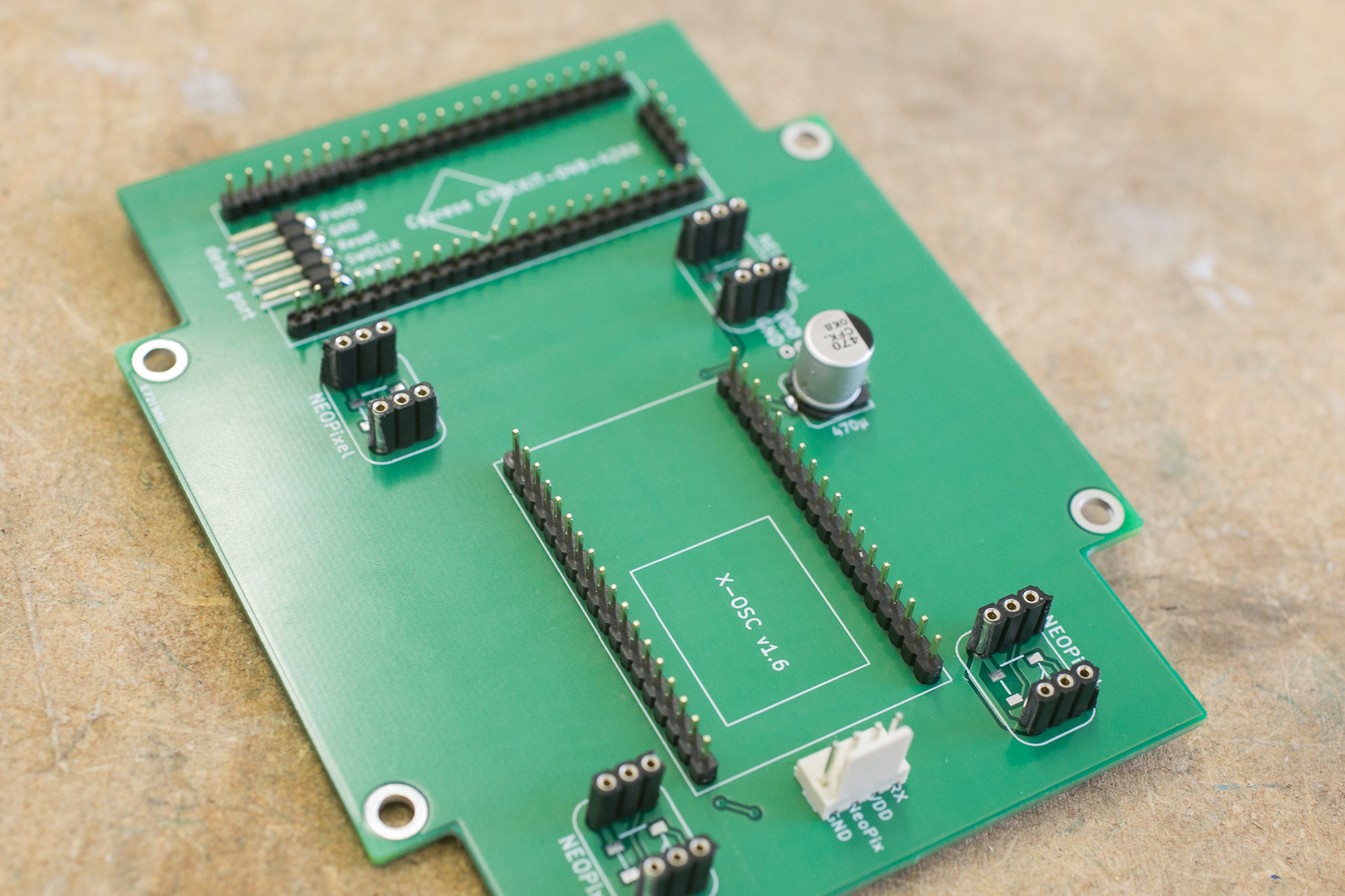 The completed board.
SMD soldering can be tricky. It is good practice to test all six capsense lines with a multimeter measuring the resistance to check if signals get through and resistance is close to 560 ohm.
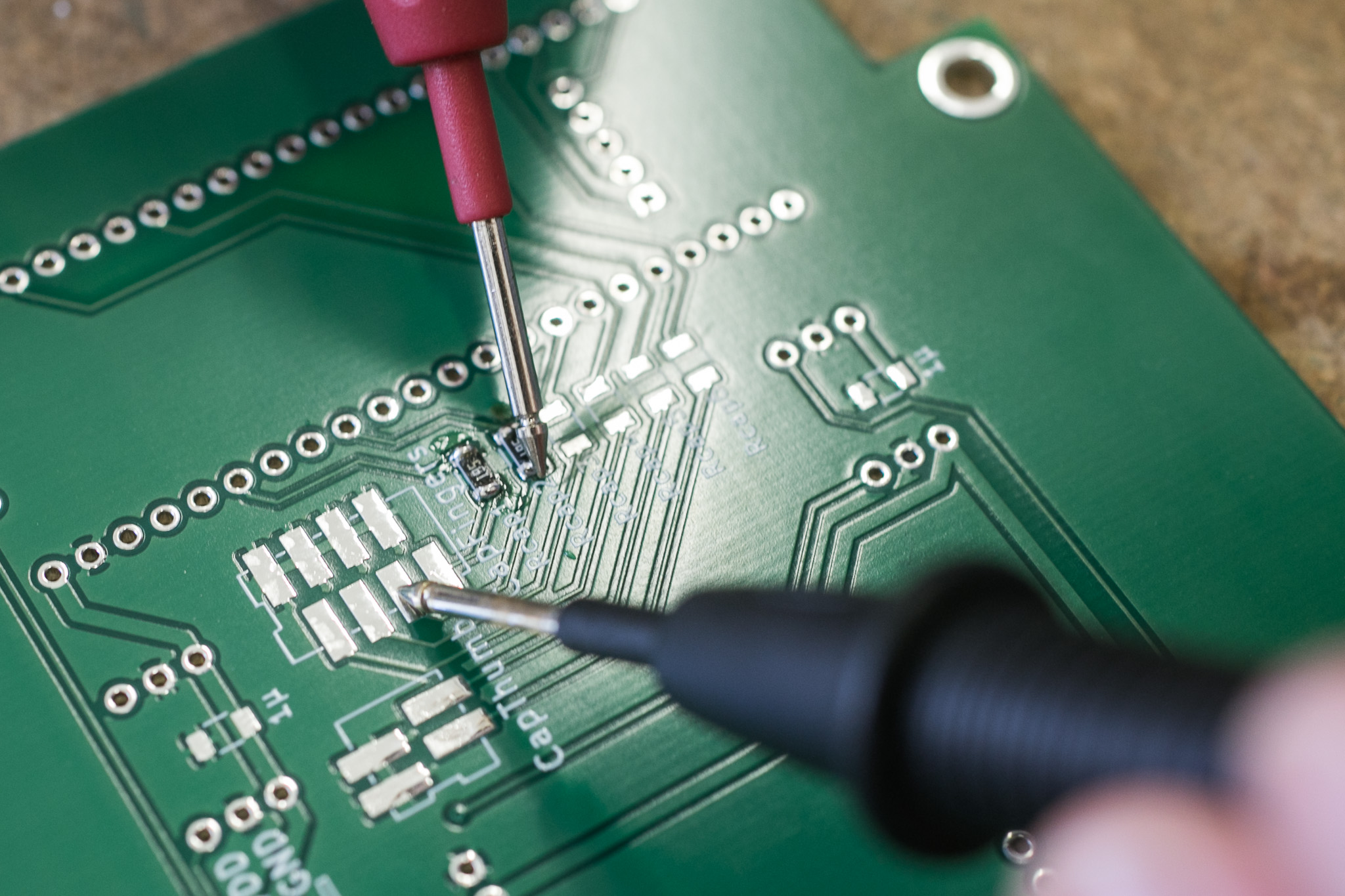 Checking correct soldering by measuring resistance.
Solder the small plugs to the capsense areas.
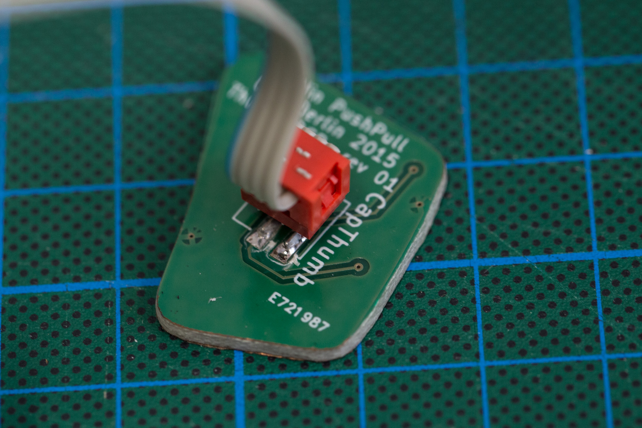 Assembled thumb sensor.
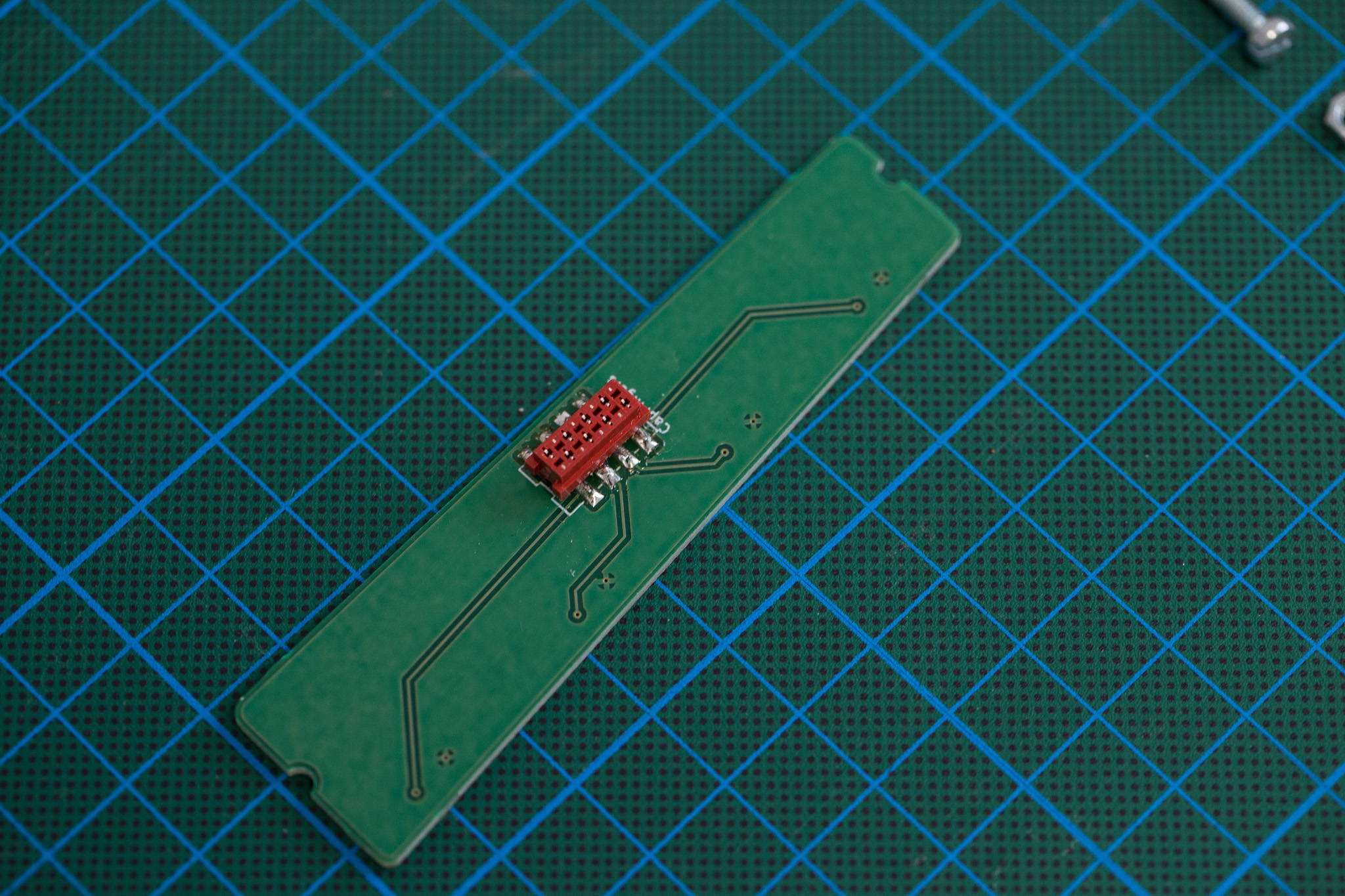 Assembled finger sensor.
Cut ribbon cables running from the mainboard to the sensor areas and crimp the plugs to them. Note the direction of the contacts; the cables should be one-to-one connections between the two ends, i.e. both plugs have to be in the same orientation. The cables should be about 10cm long.
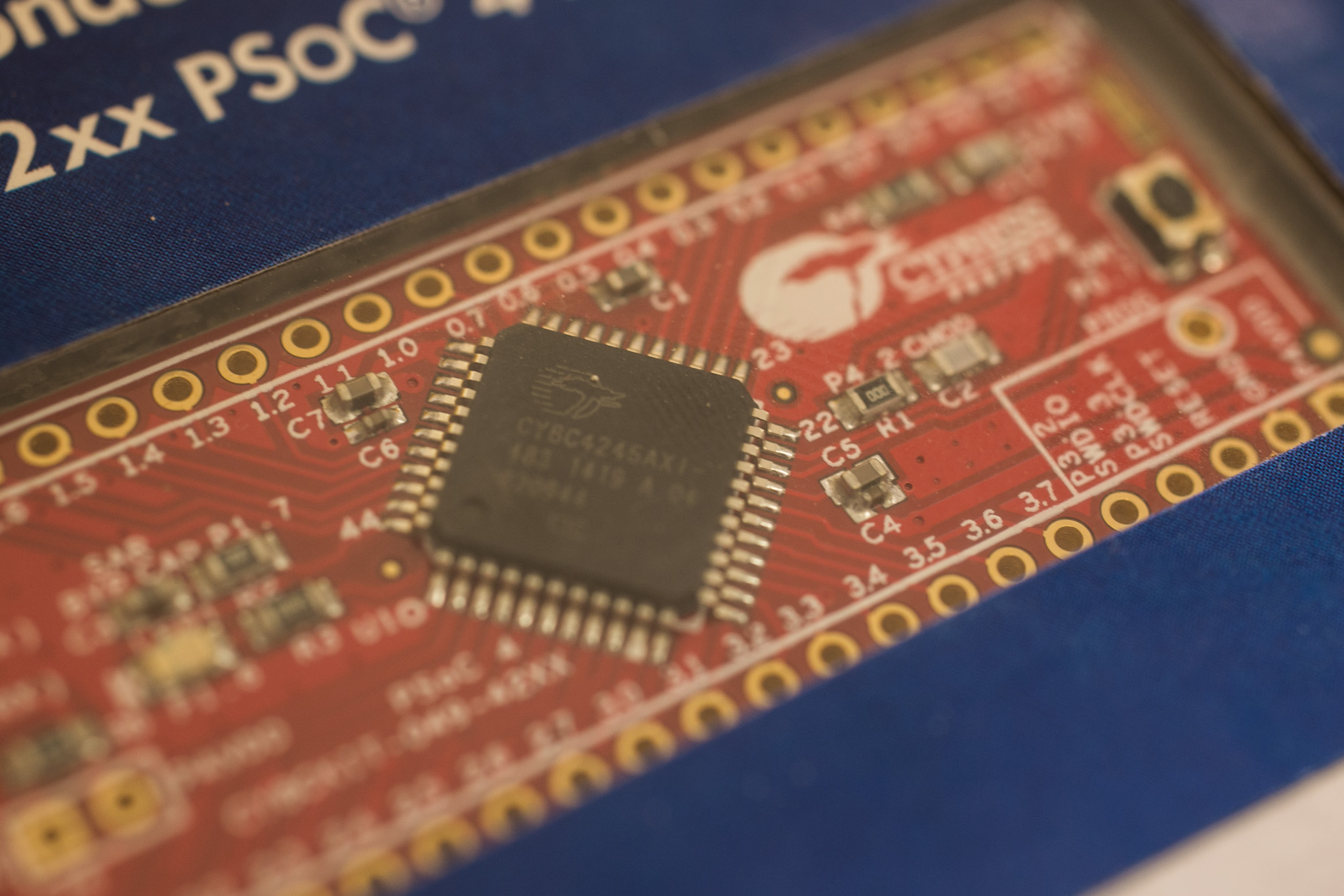
Install the code available at this repository to your PSoC4. The README of the repository gives a basic introduction on how to program the board.
You need to break away the smaller USB PCB of the PSoC board before assembling it to the main board. We used the mainboard as helping hand to solder male pin-headers straight to the PSoC. This can also be done with the NeoPixels.
Plug the PSoC board, the 4 NeoPixel LEDs and the X-OSC onto the mainboard. Take care to put them in the right directions.
This is the completed board (missing the NeoPixel’s):